Works - Great Northern Railway Caboose X187, part 2 [Works_Cabooses]
 : fig. 1, drawing process
I’m trying to create Great Northern Railway caboose X187 for my “bringin’ back the scene” project.
We can find pictures of GN caboose X187 in books and web pages. But I couldn’t find any drawings. The only information I got is that it was 70’5” long over the buffers according to “Great Northern Empire” web page. So, I tried to draw the plan from the photo.
I used the photo of brother combine GN #585 also preserved at Fort Peck, MT, because the photo was one of the clearest among photos I found.
the photo I used to deduce the plan;
I retraced the method of perspective drawing to deduce the opening arrangement of the car. Figure above shows the way I tried. Figure below shows the deduced prototype plan (This time, I planned to use MTL passenger car bodies. So, I referred to MTL’s model for elevations; windows seem rather tall and letter board is a little narrow).
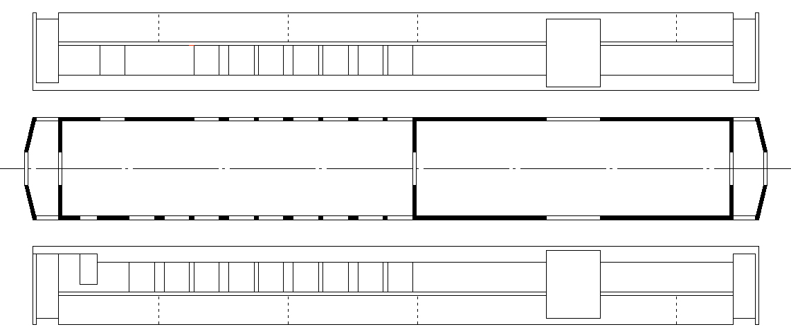 : fig. 2, deduced prototype plan
Next, I scanned the MTL body and decided the plan where to cut and join. Figure below shows the kitbashing plan. Red lined squares show the filling, while the green lined squares show the new opening.
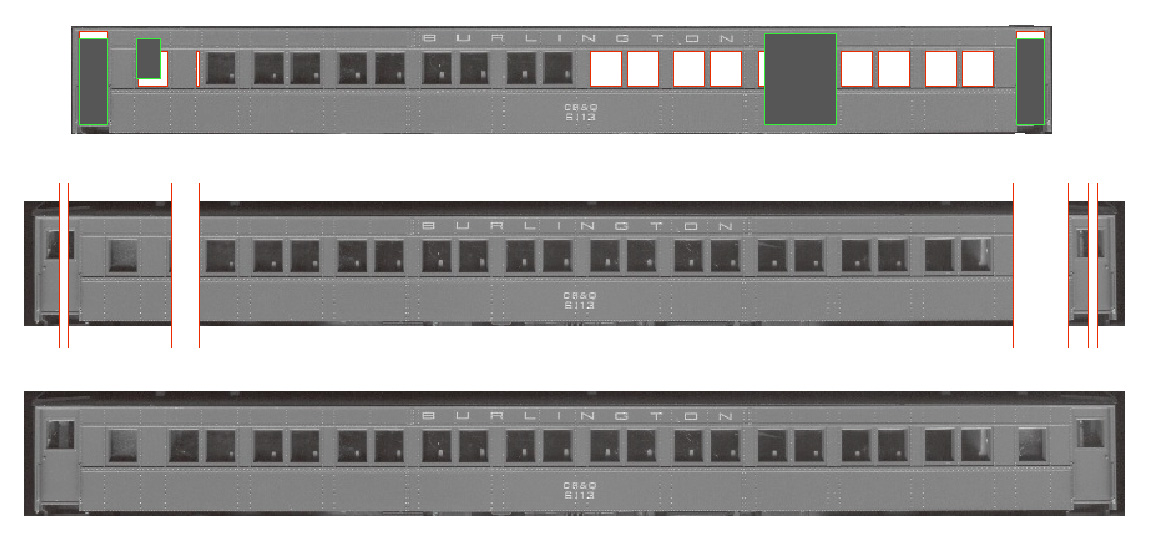 : fig. 3, kitbashing plan
GNのカブースを制作しようとしている。MTL製品を切り継ぎ工作するにせよ、必要となるのは図面である。本など探せばどこかに載っているのだろうが、今回は写真から窓割を割り出すことにした。
透視図法は、平面図などを基に、目に映る像を仮想し平面上に再現する図法である。したがって、写真を目に映った像と見なし、透視図法の手順を逆回しにたどれば、概ね正確な図面になるはずだ。この手法を示す図が上のfig. 1である。
今回はMTL製品を切り継ぎするので、高さ方向の寸法はそれに準じることになる。製品を採寸し描いた図面がfig. 2である。プロトタイプの写真と見比べると、幕板が若干狭く、窓の背が高い。
MTL製品をスキャンして、どこでどう切り継ぐか検討した図がfig. 3である。けっこう切り継ぎ箇所が多い。床や屋根を含め、全ての箇所を手ノコで直角に切る自信はない。意を決して、卓上丸ノコ盤を買った。
2013-03-22 09:00
コメント(0)
arx_Ph.D. さん

Here represented are my model railroad enthusiasm generated from the photos I took during my childhood at Knoxville, Tennessee, or from the photos I took during my recent trips.
I'm a retired professor of design, meanwhile a part-time associate at the architectural design office in Osaka, Japan where I live with my wife.


コメント 0